BUYING GUIDE / CONNECTION NOTES
USB-C Cable Testers: What the Readings Actually Prove
Pick a tester for the question you need answered. A continuity map checks wiring, an e-marker reader reads advertised cable identity, and a power meter observes a particular charging session. None of those readings alone proves high-speed signal quality, video compatibility or product safety certification.
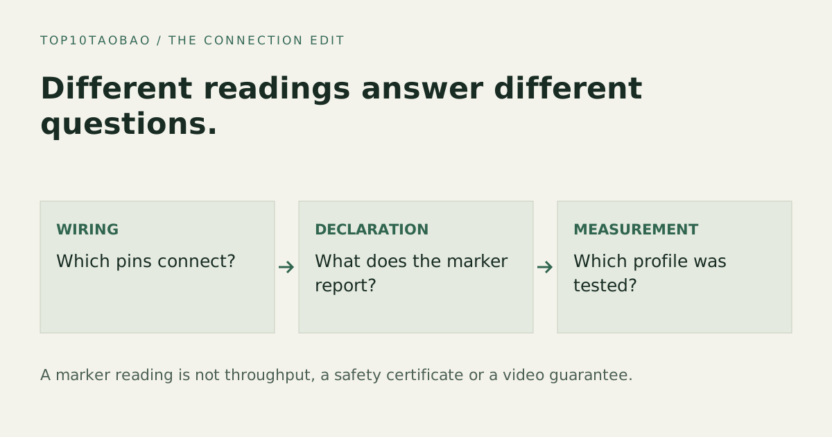
Define the claim before choosing the instrument
Start with a sentence such as “Does this cable have the conductors needed for the advertised function?” or “What current does this charger/device combination negotiate?” These are different jobs. A tester that answers one can leave the other completely unknown.
Keep the exact cable model, length and any printed rate/power markings. A missing or unreadable e-marker result is not enough to classify every cable as defective; not every cable category makes the same electronic-marking claim. Read the tester manual for supported cable types, directions and adapters.
Four common test categories and their limits
| Instrument / function | Useful evidence | Does not establish by itself |
|---|---|---|
| Continuity or pin-map tester | Connections, opens or shorts within the tester’s supported pin coverage | A high-speed eye diagram, actual throughput or durable connector quality |
| E-marker reader | Cable identity and advertised capabilities decoded from the marker | That the conductors meet every advertised capability |
| Inline USB-C power meter | Voltage/current or protocol information supported by that meter in that session | Maximum cable capability or a universal laptop charging result |
| Signal-integrity / electrical test system | Measured behavior under its profile, fixtures and specified rates | Every protocol, every active cable, or certification outside its scope |
Total Phase separates wiring, resistance, e-marker and signal-integrity testing. Its product scope is an example of why a test system’s supported rates, fixtures and profiles matter; it is not a recommendation to buy a lab instrument for ordinary cable sorting.
An e-marker declaration is not a cable benchmark
If a reader reports a power or data capability, record the field name and the cable orientation used. The result describes what the marker communicates. It does not show that a file transferred at that rate or that a connected laptop accepted the highest advertised power.
Total Phase’s e-marker reporting explanation distinguishes marker fields from other PD negotiation traffic. Use the complete instrument manual to see exactly what it observes. A photo of one “240W” reading is not a full electrical or safety report.
Likewise, a 240W cable may support only a modest data function. USB-IF distinguishes power and data capability. Keep the two labels separate when organizing cables.
A practical way to sort a cable drawer
- Separate visibly damaged cables and follow their maker’s replacement guidance. Do not stress-test suspect hardware with a valuable laptop.
- Record the cable’s known model, length and printed claims; leave unknowns unknown.
- Use a tester only in the connection and power arrangement its manual specifies.
- Save the exact result and test profile rather than relabeling a generic “pass” as “supports everything.”
- For a real device task, check that supported host/device/cable combination separately and record the observed mode.
Do not combine a power source with an unpowered pin tester unless the tester explicitly supports it. Do not use a trigger function to request a voltage beyond the attached device or fixture’s supported scope. The safe setup is instrument-specific, not a universal wiring recipe.
Interpret two plausible results carefully
The cable charges a phone but the monitor stays blank: charging success proves only that observed power session. Check the cable’s video/data conductors and the host/monitor path. Use the video-support checklist rather than concluding that the monitor is faulty.
An e-marker reader reports a high data rate but a transfer is slow: first verify the exact host port, device and selected connection. Then consider the workload and whether an appropriate signal test is needed. The marker is a claim to investigate, not a measured sustained speed.
For laboratory work, the Total Phase manual shows separate resistance and signal test results. Its scope and profiles must be read before interpreting a pass/fail output.
Buy only the level of evidence you need
For sorting known cables by intended use, clear manufacturer identification and a task-specific connection check may be enough. For checking marker identity, choose a reader with documented field support. For incoming production quality or a disputed high-speed claim, define the electrical tests, rates and fixtures first; a pocket meter may not be an adequate substitute.
This page explains instrument categories from public documentation. We have not physically tested or ranked the instruments. A vendor test report is not automatically USB-IF certification; check the applicable certification record separately. Continue with the cable capability checklist and link-rate explanation.
Sources & scope
Published specifications and standards explain possible capabilities. They do not verify a complete combination of your computer, cable, adapter and peripheral. No physical product test is claimed.